• Home
  • Download PDF
  • Order CD-ROM
  • Order in Print
Figure 7. Throttle and Auxiliary Hydraulic Controls.
Figure 9. Cab Door Latch.

Operators Manual For M400T And M400W
Page Navigation
  26    27    28    29    30  31  32    33    34    35    36  
img
. .
TM 5-3805-292-10
0004
OPERATOR CONTROLS AND INDICATORS CONTINUED
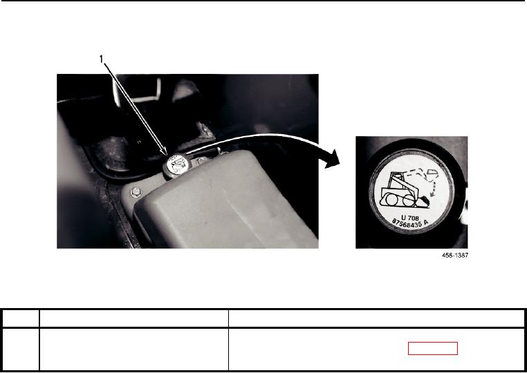
Figure 8. Boom Override Valve.
0004
KEY
COMPONENT
DESCRIPTION
1
Boom Override Valve
Allows lift arm to be lowered when engine has stopped. Refer
to Operation Under Usual Conditions (WP 0005). Located on
left side of operator seat.
0004-9


Privacy Statement
Press Release
Contact

© Copyright Integrated Publishing, Inc.. All Rights Reserved.