
TM 5-3805-292-23
0003
COOLING SYSTEM
0003
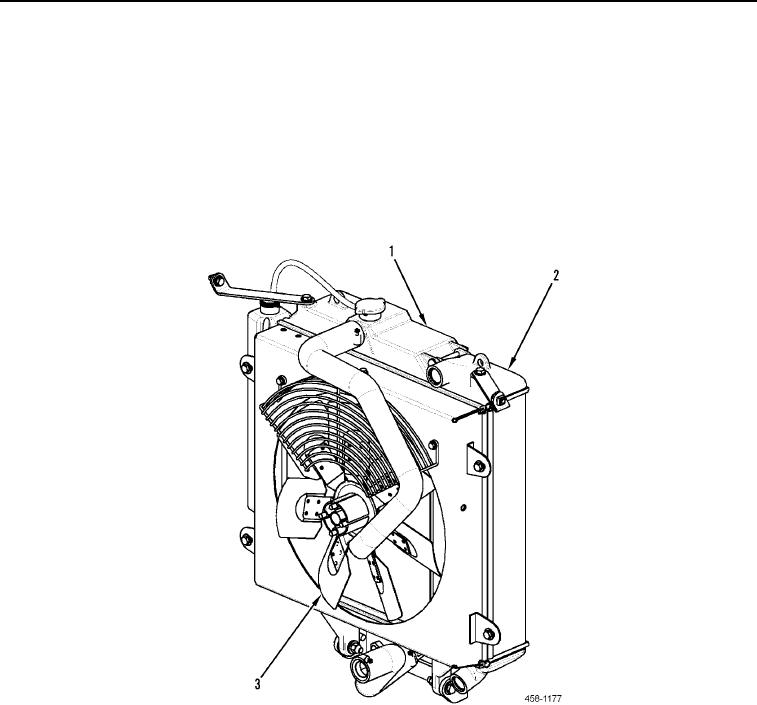
1. ENGINE COOLANT RADIATOR (Figure 3, Item 1) allows cooling of the engine coolant. As the coolant
circulates, it passes through the coolant radiator. Air is drawn over the coolant radiator by the engine cooling
fan and removes excess heat.
2. COMBINATION COOLER HYDRAULIC OIL SECTION (Figure 3, Item 2) allows cooling of the hydraulic oil. As
the oil circulates, it passes through the hydraulic oil cooler. Air is drawn over the cooler radiator by the engine
cooling fan and removes excess heat.
3. ENGINE COOLING FAN (Figure 3, Item 3) draws air through the cooling pack and circulates it around the
engine compartment. The cooling fan is driven via a drivebelt from the engine crankshaft.
Figure 3. Cooling System.
0003