TM 5-3805-292-23
0003
STEERING SYSTEM CONTINUED
2. ANTI-STALL SYSTEM. With the anti-stall system, pilot hand control supply pressure is typically lower than the
hydrostatic system charge pressure. Hydrostatic pump charge pressure is supplied to the anti-stall control
cartridge. As the engine speed increases, the anti-stall cartridge delivers a higher control pressure to the
joystick control valve. When the engine is at low idle, the pressure from the anti-stall cartridge will be lower.
The lower the control pressure, the slower the maximum machine travel speed. Control oil pressure from the
anti-stall regulating cartridge is directed to the travel control pilot hand control valve through the control
interlock solenoid valve. Hydrostatic pump displacement is infinitely variable in each direction of travel,
proportional to pump drive speed, travel pressure, and the location of the pilot hand control handle. Travel
direction is controlled by moving the pilot hand control handle either in the forward or backward direction.
Steering is controlled by moving the hand control side to side while having the lever either in the forward or
backward position. Counter-rotation is controlled by moving the control handle side to side from the neutral
position.
3. PILOT HAND CONTROL JOYSTICK VALVE ASSEMBLY. In the neutral position, all of the hydrostatic pump
travel control ports are connected to the tank. This tank connection is made through the joystick valve. The
pilot hand control joystick valve assembly has four control spools. Any time one or more of these spools are
not actuated, the travel port for the spool is connected to the tank through a drilling in the spool. The supply
pressure from the hydrostatic pump anti-stall valve is completely blocked off at all four control spools at this
time. The travel control spool in the joystick is not directly connected to the actuating lever/plunger. There is a
spring between the plunger and the control spool.
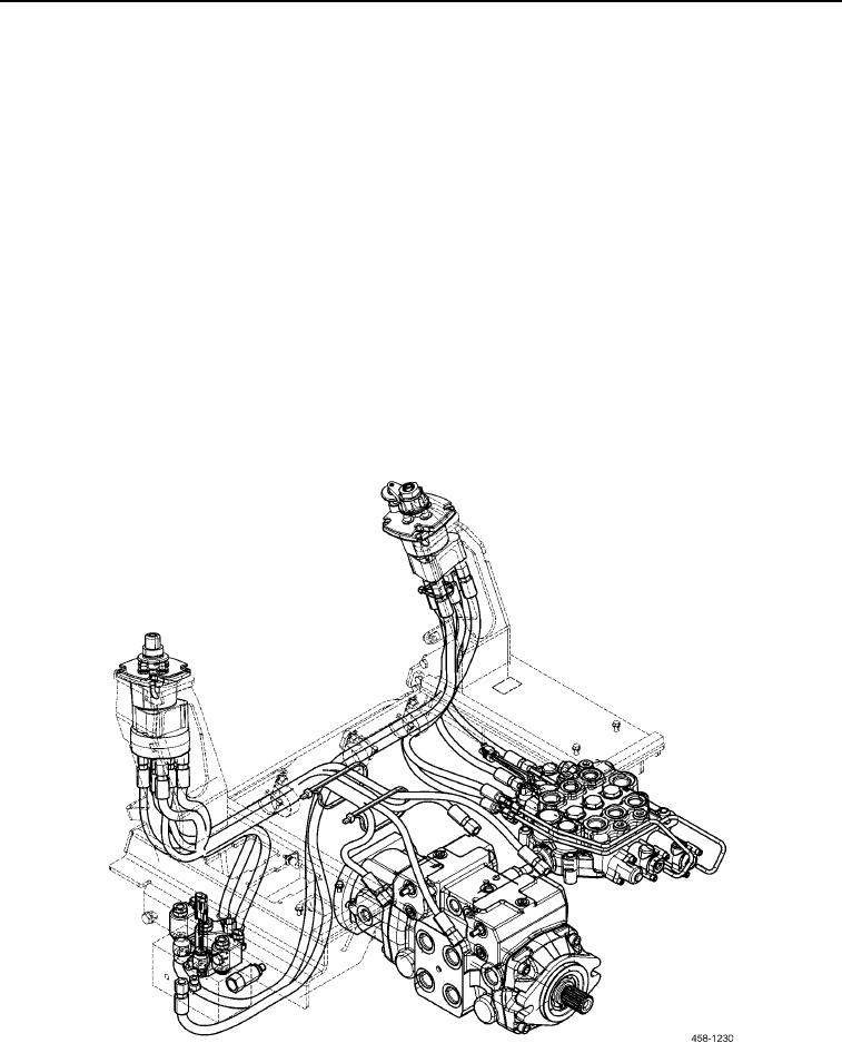
Figure 6. ISO Pattern Pilot Travel Control System.
0003

