
TM 5-3805-292-23
0021
INSTALLATION CONTINUED
N OT E
Install washers as noted during removal.
7. Install ten washers (Figure 12, Items 2 and 4), six bolts (Figure 12, Items 3 and 5), and two spacers (Figure 12,
Item 1) on engine mounting bracket (Figure 12, Item 6). Torque bolts to 66 to 73 lb-ft (90 to 100 Nm).
1 (HIDDEN)
2,3
458-1058
6
4,5
Figure 12. Engine Mounting Bracket.
0021
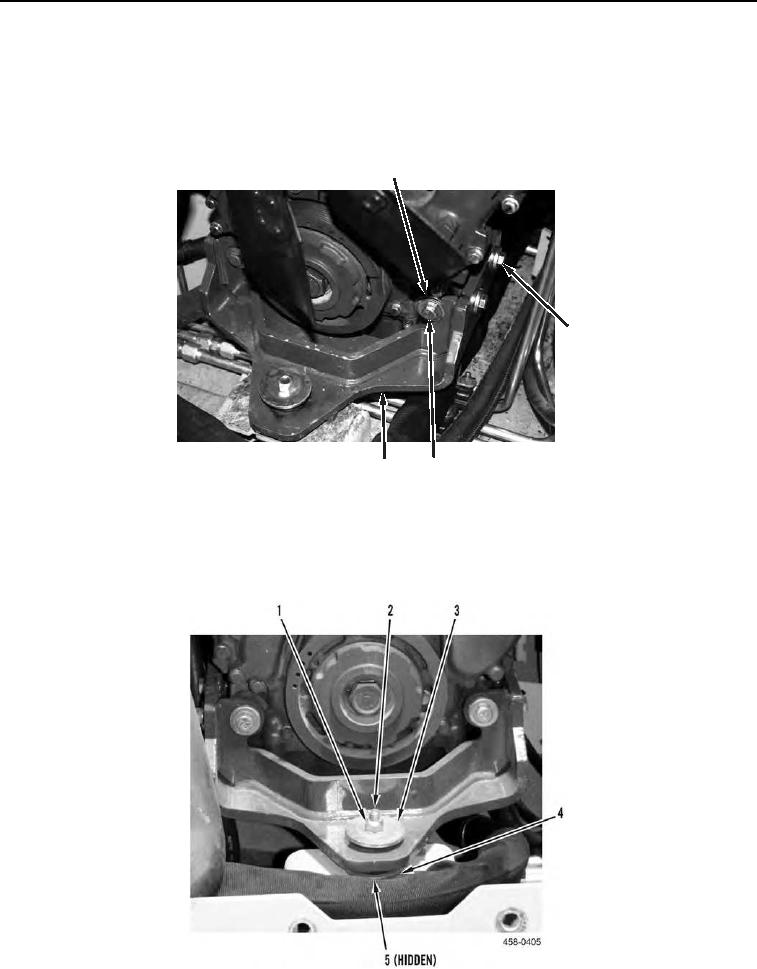
8. Tighten washer (Figure 13, Item 5), washer (Figure 13, Item 4), bolt (Figure 13, Item 2), washer (Figure 13,
Item 3), and nut (Figure 13, Item 1) on engine mount. Torque to 66 to 73 lb-ft (90 to 100 Nm).
Figure 13. Engine Mount.
0021