
TM 5-3805-292-23
0021
INSTALLATION CONTINUED
N OT E
Install new tiedown straps as needed.
Install lockwashers as noted during removal.
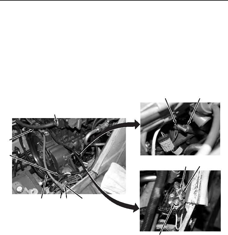
15. Position five wires (Figure 17, Item 4) on two terminals (Figure 17, Item 7) and install three new lockwashers
(Figure 17, Item 6) and four nuts (Figure 17, Item 5).
16. Connect heater hose (Figure 17, Item 14) to engine and attach clamp (Figure 17, Item 1).
17. Position engine ground wires (Figure 17, Item 3) on engine and install nut (Figure 17, Item 2).
18. Connect electrical connector (Figure 17, Item 13).
19. Install cable (Figure 17, Item 12), new lockwasher (Figure 17, Item 10), and nut (Figure 17, Item 9) on termi-
nals (Figure 17, Item 8) and position protective cover (Figure 17, Item 11).
3
2
1
14
13
4
5,6 (HIDDEN)
8
9,10
11
12
458-1056
7
Figure 17. Engine Hose and Electrical Connections.
0021
END OF TASK