
TM 5-3805-292-23
0021
INSTALLATION CONTINUED
9. Remove lifting device from engine assembly.
10. Install control rod (Figure 14, Item 4) on end of throttle actuator-to-engine linkage (Figure 14, Item 1).
11. Connect hose (Figure 14, Item 3) to fitting (Figure 14, Item 2).
12. Connect hose (Figure 14, Item 5) to engine.
1
458-1095
5
3
4
2
Figure 14. Hoses and Throttle Linkage.
0021
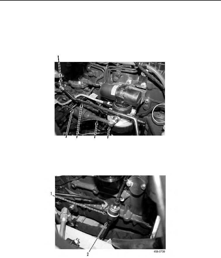
13. Connect hose (Figure 15, Item 2) to inline fuel filter (Figure 15, Item 1).
Figure 15. Inline Fuel Filter and Hose.
0021