
TM 5-3805-292-23
0039
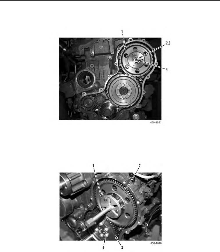
REMOVAL CONTINUED
4. Remove nut (Figure 4, Item 2) and washer (Figure 4, Item 3) from fuel injection pump shaft (Figure 4, Item 4).
Figure 4. Camshaft Gear and Fuel Injection Pump Gear.
0039
5. Use removal tool (Figure 5, Item 1) to remove fuel injection pump gear (Figure 5, Item 2) from engine.
6. Remove six flanged bolts (Figure 5, Item 4) and camshaft gear (Figure 5, Item 3) from engine.
Figure 5. Removal Tool.
0039