
TM 5-3805-292-23
0039
INSTALLATION CONTINUED
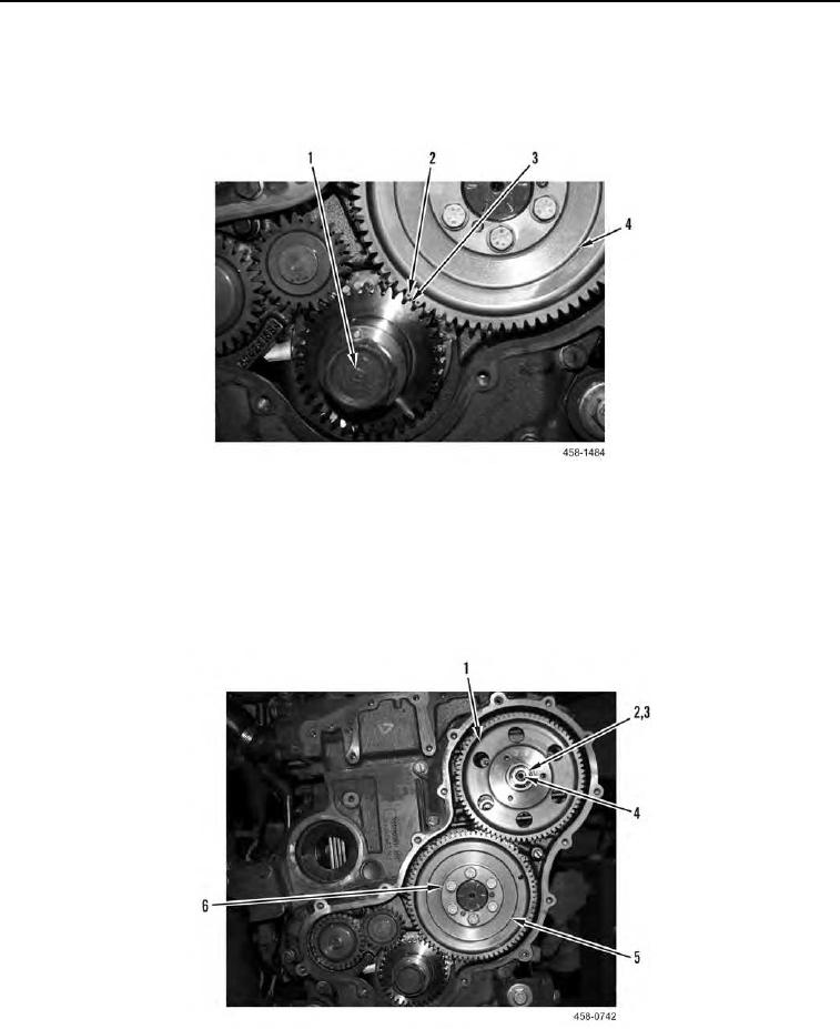
4. Position crankshaft gear (Figure 11, Item 1) and camshaft gear (Figure 11, Item 4) and camshaft gear (Figure
11, Item 4) on engine, making sure two dotted teeth (Figure 11, Item 2) on camshaft gear flank beveled tooth
(Figure 11, Item 3) of crankshaft gear.
Figure 11. Aligning Crankshaft Gear.
0039
5. Install six flanged bolts (Figure 12, Item 6) on camshaft gear (Figure 12, Item 5). Tighten bolts to 23 to 30 lb-ft
(32 to 40 Nm).
6. Position fuel injection pump gear (Figure 12, Item 1) on engine and loosely install washer (Figure 12, Item 3)
and nut (Figure 12, Item 2) on injection pump shaft (Figure 12, Item 4). Tighten nut to 15 to 21 lb-ft (20 to 28
Nm).
Figure 12. Camshaft Gear and Injection Fuel Pump Gear.
0039