TM 5-3805-292-23
0058
INSTALLATION CONTINUED
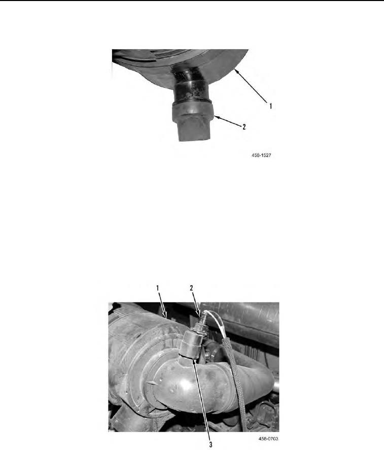
4. Install safety relief valve (Figure 12, Item 2) on air cleaner assembly (Figure 12, Item 1).
Figure 12. Relief Valve.
C AU T I O N
DO NOT overtighten air restriction switch. Failure to follow this caution may result in
damage to equipment.
5. Install air restriction switch (Figure 13, Item 3) on air cleaner assembly (Figure 13, Item 1).
N OT E
Install wiring harness as tagged during removal.
6. Connect electrical connector (Figure 13, Item 2) to air restriction switch (Figure 13, Item 3).
Figure 13. Air Restriction Switch.
0058
END OF TASK

