
TM 5-3805-292-23
0059
REMOVAL CONTINUED
N OT E
Tag lines and hoses to add in installation.
Cap lines, fittings, and hoses.
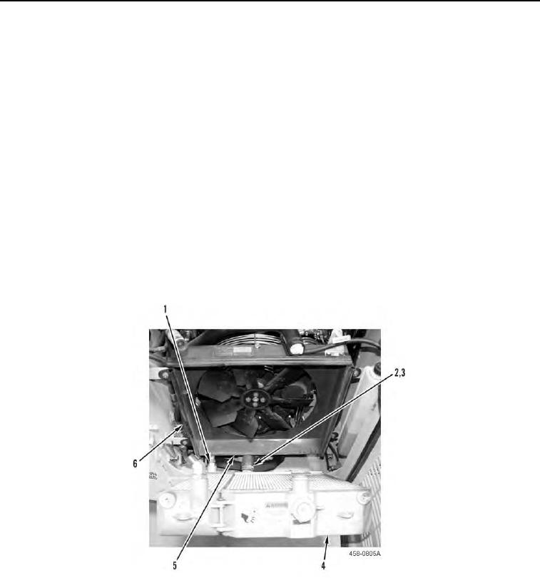
6. Tilt module (Figure 2, Item 4) to access line (Figure 2, Item 1) and hose (Figure 2, Item 3).
7. Remove seal (Figure 2, Item 6) from bottom of fan shroud (Figure 2, Item 5).
8. Disconnect line (Figure 2, Item 1), loosen clamp (Figure 2, Item 2), and disconnect hose (Figure 2, Item 3) from
module (Figure 2, Item 4).
C AU T I O N
Do not allow drain valve to rest on surface. Failure to follow this caution may result in
damage to equipment.
N OT E
Module weighs 60 lb (27 kg).
9. With assistance, remove module (Figure 2, Item 4) from machine and place on a flat surface.
Figure 2. Hose and Clamp.
0059
END OF TASK