
TM 5-3805-292-23
0085
INSTALLATION
00085
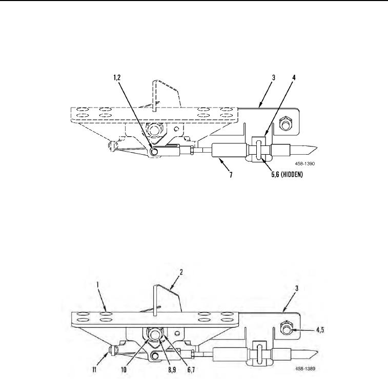
1. Install spacer (Figure 4, Item 4), cable (Figure 4, Item 7), U-bolt (Figure 4, Item 5), and two nuts (Figure 4, Item
6) on support mounting plate (Figure 4, Item 3).
2. Install cable (Figure 4, Item 7), clevis pin (Figure 4, Item 1), and new cotter pin (Figure 4, Item 2) on machine.
Figure 4. Auxiliary Hydraulic Cable.
0085
3. Install bolt (Figure 5, Item 10), plate (Figure 5, Item 3), pedal lock lever (Figure 5, Item 2), spring (Figure 5, Item
11), rubber spacer (Figure 5, Item 9), auxiliary hydraulic pedal (Figure 5, Item 1), bushing (Figure 5, Item 8),
washer (Figure 5, Item 7), and nut (Figure 5, Item 6) on machine.
4. Install bolt (Figure 5, Item 5) and nut (Figure 5, Item 4) on bracket (Figure 5, Item 3).
Figure 5. Auxiliary Hydraulic Pedal.
0085
END OF TASK
ADJUSTMENT
00085
N OT E
Make sure the auxiliary spool in the control valve is in the neutral position.
Adjust cable (Figure 4, Item 7) until auxiliary hydraulic pedal (Figure 5, Item 1) is in horizontal position. Tighten nuts
(Figure 4, Item 6).