
TM 5-3805-292-23
0084
INSTALLATION CONTINUED
N OT E
Use nut retained from removal procedure.
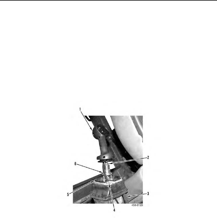
3. Install nut (Figure 4, Item 2) on control handle (Figure 4, Item 1).
N OT E
Rotate handle in all directions before tightening nut to its final locked position to ensure
the control handle does not come in contact with any part of the cab.
4. Install control handle (Figure 4, Item 1) on joystick valve (Figure 4, Item 5).
5. Position joystick valve (Figure 4, Item 5) in forward position to allow routing of control handle harness (Figure
4, Item 6) through console bracket (Figure 4, Item 3).
6. Connect control handle harness (Figure 4, Item 6) to chassis harness.
7. Install three screws (Figure 4, Item 4) on joystick valve (Figure 4, Item 5).
Figure 4. Control Handle.
0084
END OF TASK