
TM 5-3805-292-23
0106
DISASSEMBLY CONTINUED
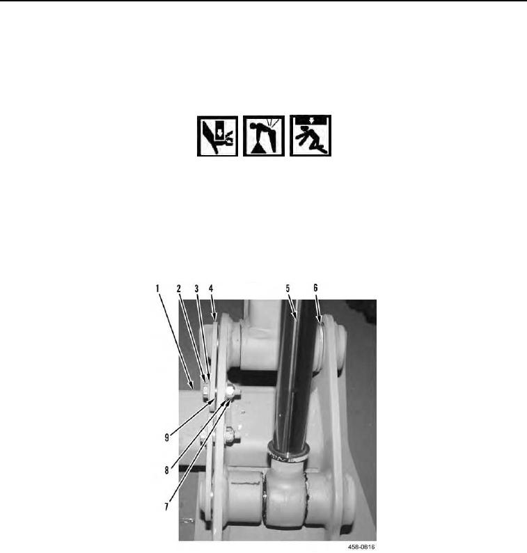
5. Remove two nuts (Figure 8, Item 7), washers (Figure 8, Item 8), bolts (Figure 8, Item 2), washers (Figure 8,
Item 3), spacers (Figure 8, Item 9), pins (Figure 8, Item 4), and washer (Figure 8, Item 6) from coupler (Figure
8, Item 1).
6. Repeat step 5 to remove opposite side.
WARN I N G
Use caution when handling heavy components. Provide adequate support and use
assistance. Failure to follow this warning may result in injury or death to personnel and
damage to equipment.
N OT E
Coupler weighs 130 lbs (58.9 kg).
7. Remove coupler (Figure 8, Item 1) and tilt cylinder (Figure 8, Item 5) from loader arm.
Figure 8. Coupler.
0106