
TM 5-3805-292-23
0106
ASSEMBLY
000106
N OT E
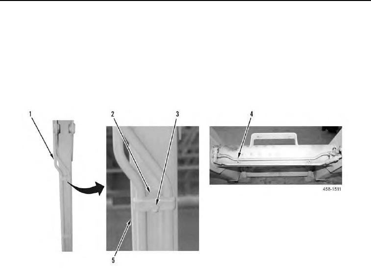
Install hydraulic lines for tilt cylinders as noted during removal.
1. Install four hydraulic lines (Figure 11, Items 1 and 4), five clamps (Figure 11, Item 2), and bolts (Figure 11, Item
3) on loader arm (Figure 11, Item 5).
2. Install two hydraulic lines (Figure 11, Items 1 and 4) for attachment coupler, four clamps (Figure 11, Item 2) and
bolts (Figure 11, Item 3).
Figure 11. Lines and Clamps.
0106