
4
TM 5-3805-292-23
FIELD MAINTENANCE
-
LOADER ARM SUPPORT STRUT REPLACEMENT
0107
REMOVAL, CLEANING AND INSPECTION, INSTALLATION
INITIAL SETUP
References
Tools and Special Tools
0
0
Tool Kit, General Mechanic's (WP 0178, Item
TM 5-3805-292-10
0
33)
TM 5-3805-292-23P, Figure 60
0
0
SATS (WP 0178, Item 30)
0
Estimated Time to Complete
0
Materials/Parts
0.3 Hr
0
0
Cleaning Compound, Solvent, Type III (WP
0179, Item 3)
0
Rag, Wiping (WP 0179, Item 19)
0
REMOVAL
000107
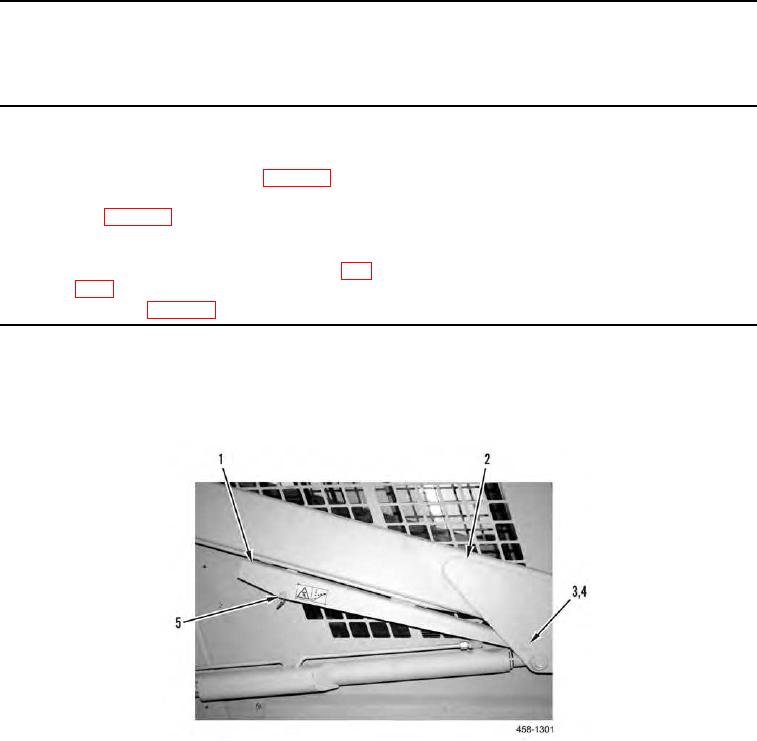
1. Remove two retaining rings (Figure 1, Item 3) and pin (Figure 1, Item 4) from loader arm (Figure 1, Item 2).
2. Remove pin (Figure 1, Item 5) and strut (Figure 1, Item 1) from loader arm (Figure 1, Item 2).
Figure 1. Loader Support Strut.
0107
END OF TASK