
TM 5-3805-292-23
0124
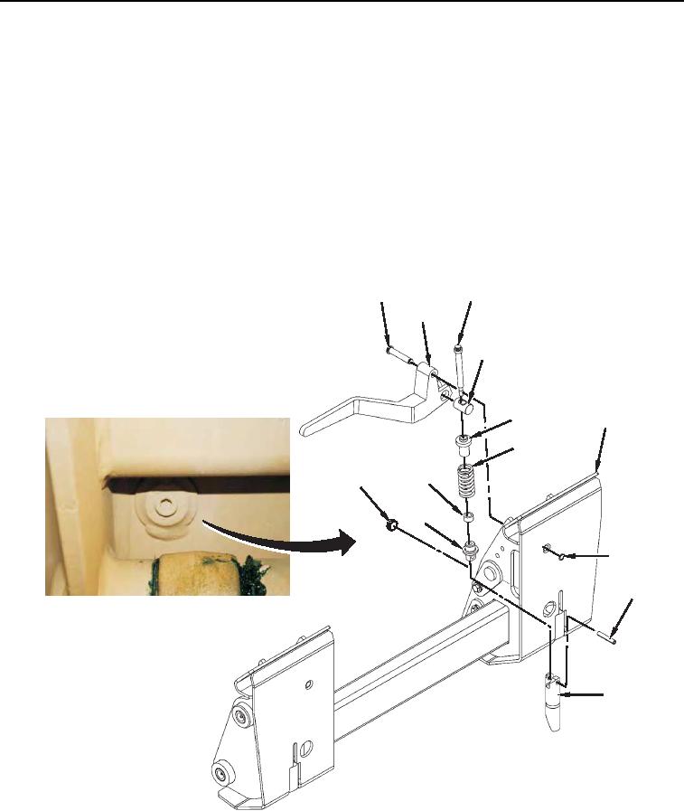
DISASSEMBLY
000124
N OT E
This procedure is for disassembly of one handle. Repeat procedure for second handle.
1. Remove plug (Figure 2, Item 12) and pin (Figure 2, Item 9) from coupler (Figure 2, Item 7). Discard pin.
2. Remove retaining ring (Figure 2, Item 8) and pin (Figure 2, Item 1) from coupler (Figure 2, Item 7).
N OT E
Note orientation of latch pin to aid in installation.
3. Lift handle (Figure 2, Item 2) until retaining pin (Figure 2, Item 11) disengages latch pin (Figure 2, Item 10).
4. Remove handle (Figure 2, Item 2) and latch pin (Figure 2, item 10) from coupler (Figure 2, Item 7).
5. Remove bolt (Figure 2, Item 3), spring (Figure 2, Item 6), sleeve (Figure 2, Item 13), guide (Figure 2, Item 5),
pin (Figure 2, Item 4), and retaining pin (Figure 2, Item 11) from handle (Figure 2, Item 2).
3
1
2
4
5
7
6
13
12
11
8
9
10
458-1091
Figure 2. Coupler Disassembly.
0124
END OF TASK