TM 5-3805-292-23
0124
ASSEMBLY CONTINUED
N OT E
Install latch pin as noted during removal.
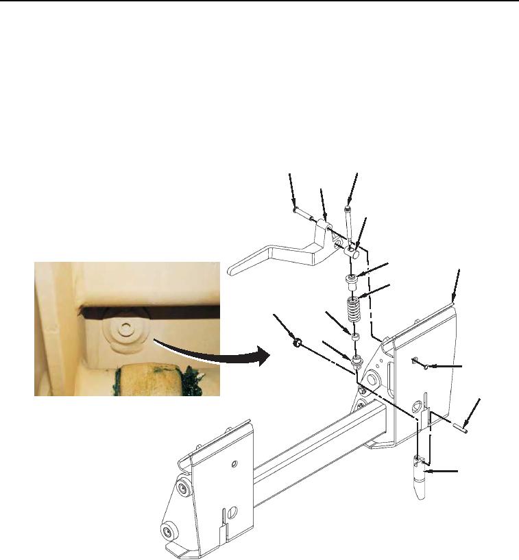
2. Install latch pin (Figure 3, item 10) and handle (Figure 3, Item 2) on coupler (Figure 3, Item 7).
3. Install pin (Figure 3, Item 1) and retaining ring (Figure 3, Item 8) on coupler (Figure 3, Item 7).
4. Install new pin (Figure 3, Item 9) and sleeve (Figure 3, Item 13) on coupler (Figure 3, Item 7).
5. Install plug (Figure 3, Item 12).
3
1
2
4
5
7
6
13
12
11
8
9
10
458-1091
Figure 3. Coupler Assembly.
0124
END OF TASK

