
TM 5-3805-292-23
0145
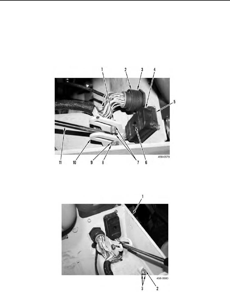
INSTALLATION CONTINUED
5. Install rectangular connector (Figure 12, Item 4) in socket (Figure 12, Item 5) on bulkhead. Tighten bolt (Figure
12, Item 6).
6. Align locating tab of round connector bezel (Figure 12, Item 2) with space in socket (Figure 12, Item 3) and
install round connector on socket. Tighten bezel.
7. Position support lift rod (Figure 12, Item 11) on bracket (Figure 12, Item 10).
8. Position support lift rod (Figure 12, Item 11) between two spacers (Figure 12, Item 7) on bracket (Figure 12,
Item 10) and install bolt (Figure 12, Item 1), washer (Figure 12, Item 9), and nut (Figure 12, Item 8) on bracket.
Figure 12. Bulkhead Connectors.
0145
9. Install two ground wires (Figure 13, Item 3) and bolt (Figure 13, Item 2) on ROPS assembly (Figure 13, Item 1).
Figure 13. Ground Wires.
0145