
TM 5-3805-292-23
0145
INSTALLATION
000145
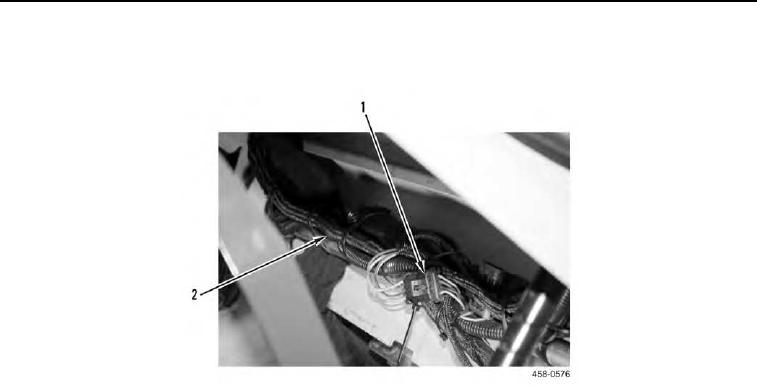
1. Connect cab wiring (Figure 9, Item 2) to connector (Figure 9, Item 1).
Figure 9. ROPS Front Interior.
0145
N OT E
Tape connectors to cab wiring harness fo ease of installation on ROPS assembly.
r
Install electrical components as tagged during removal.
Install tiedown straps to secure cab wiring harness.
2. Install LH leg of cab wiring harness (Figure 10, Item 1) through channel in ROPS assembly.
3. Connect two connectors (Figure 10, Item 2) to upper LH side of cab wiring harness (Figure 10, Item 1).