• Home
  • Download PDF
  • Order CD-ROM
  • Order in Print
Figure 6. Cab Wiring Harness (RH Leg).
Figure 8. ROPS Interior Front.

Field Maintenance Manual For M400T And M400W
Page Navigation
  960    961    962    963    964  965  966    967    968    969    970  
img
.
TM 5-3805-292-23
0145
REMOVAL CONTINUED
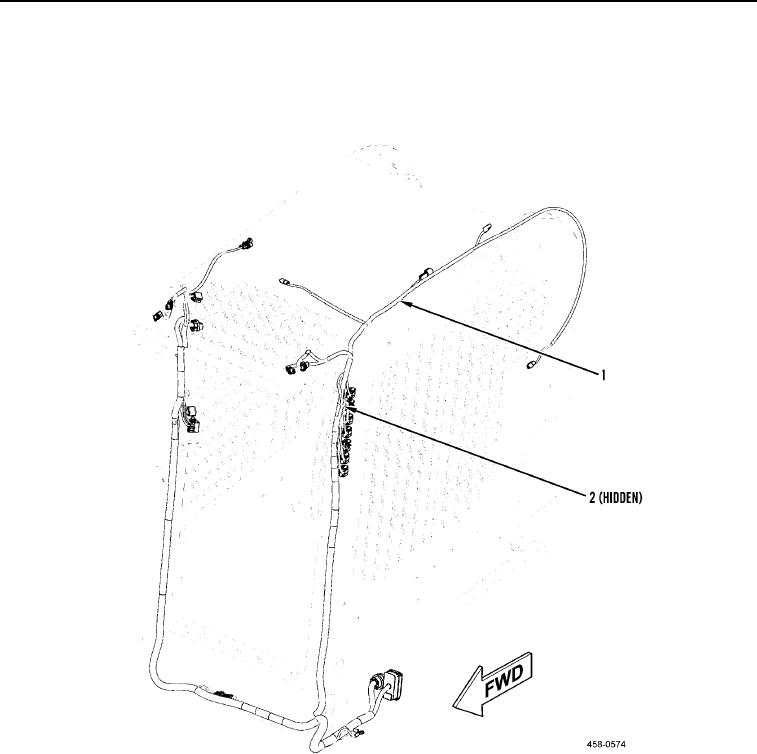
13. Disconnect remaining two connectors (Figure 7, Item 2) from upper LH side of cab wiring harness (Figure 7,
Item 1).
14. Pull LH leg of cab wiring harness (Figure 7, Item 1) out of channel in ROPS assembly.
Figure 7. Cab Wiring Harness (LH Leg).
0145
0145-6


Privacy Statement
Press Release
Contact

© Copyright Integrated Publishing, Inc.. All Rights Reserved.