
TM 5-3805-292-23
0171
ASSEMBLY CONTINUED
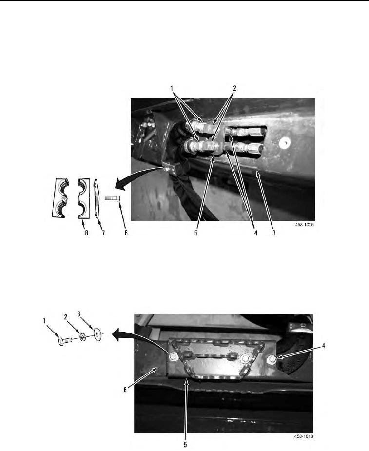
18. Install hydraulic plate (Figure 15, Item 5) and two 90 elbows (Figure 15, Item 2) on assembly.
19. Connect two tees (Figure 15, Item 4) to two 90 elbows (Figure 15, Item 2).
20. Connect two hoses (Figure 15, Item 1) to two 90 elbows (Figure 15, Item 2).
21. Position hose cushion (Figure 15, Item 8) and plate (Figure 15, Item 7) and install capscrew (Figure 15, Item 6)
on back blade (Figure 15, Item 3).
Figure 15. Bucket Hoses.
0171
22. Position hydraulic cover (Figure 16, Item 5) on back blade (Figure 16, Item 6).
23. Install two washers (Figure 16, Item 3), new lockwashers (Figure 16, Item 2), and capscrews (Figure 16,
Item 1) on hydraulic cover (Figure 16, Item 5).
24. Tighten capscrew (Figure 16, Item 4).
Figure 16. Hydraulic Cover.
0171
END OF TASK
0171-11