
TM 5-3805-292-23
0171
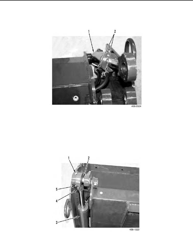
ASSEMBLY CONTINUED
12. Install hose assemblies with tees (Figure 13, Item 2) on assembly.
13. Pull cylinder (Figure 13, Item 1) back and connect two hoses (Figure 13, Item 2) to cylinder.
Figure 13. Cylinder Hoses.
0171
14. Align assembly and install upper cylinder pin (Figure 14, Item 2) on assembly.
15. Install capscrew (Figure 14, Item 1) and new locknut (Figure 14, Item 5) on upper cylinder pin (Figure 14, Item
2).
16. Install grease fitting (Figure 14, Item 4) on cylinder (Figure 14, Item 3).
17. Repeat steps 13 through 16 for other side.
Figure 14. Upper Cylinder.
0171
0171-10