
TM 5-3805-292-23
0171
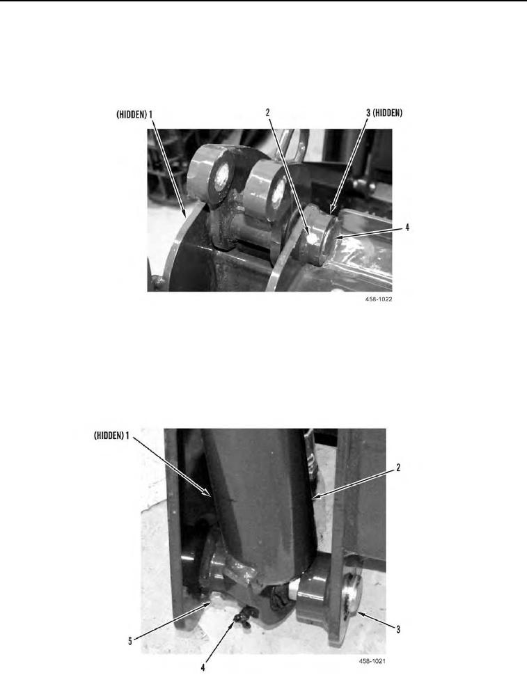
ASSEMBLY CONTINUED
4. Align bores and install clamshell pivot pin (Figure 11, Item 4) on assembly.
5. Install capscrew (Figure 11, Item 2) and new locknut (Figure 11, Item 3) on pivot pin (Figure 11, Item 4).
6. Install new grease fitting (Figure 11, Item 1) on clamshell pivot pin (Figure 11, Item 4).
7. Repeat steps 4 through 6 for other side.
Figure 11. Clamshell Pivot Pin.
0171
8. Position cylinder (Figure 12, Item 2) on assembly and install lower cylinder pin (Figure 12, Item 3).
9. Install capscrew (Figure 12, Item 5) and new locknut (Figure 12, Item 1) on lower cylinder pin (Figure 12, Item
3).
10. Install new grease fitting (Figure 12, Item 4) on cylinder (Figure 12, Item 2).
11. Repeat steps 8 through 10 for other side.
Figure 12. Lower Cylinder.
0171
0171-9