• Home
  • Download PDF
  • Order CD-ROM
  • Order in Print
Figure 34. Pilot Valve Cover.
Figure 36. Shaft and Fork and Bucket Kickout Position Sensors Mounting Hardware.

Field Maintenance Manual For 924H Wheel Loader -2 Page Navigation
  241    242    243    244    245  246  247    248    249    250    251  
img
.
TM 5-3805-298-23-2
0155
Table 1. Kickout System Will Not Operate or Operates Improperly Continued.
0155
MALFUNCTION
TEST OR INSPECTION
CORRECTIVE ACTION
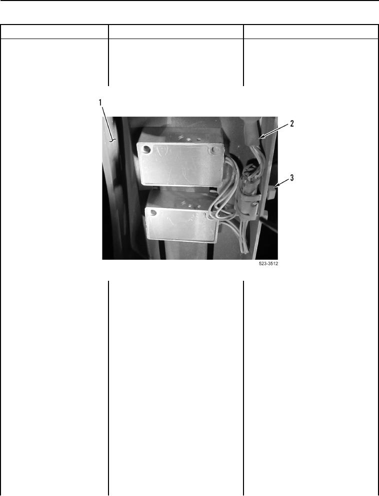
8. If removed, install two new tiedown
Kickout System Will Not
straps (Figure 35, Item 3) on wiring
Operate or Operates
harness (Figure 35, Item 2) and
Improperly - Continued
mounting bracket (Figure 35,
Item 1).
Figure 35. Tiedown Straps.
0155
0155-63


Privacy Statement
Press Release
Contact

© Copyright Integrated Publishing, Inc.. All Rights Reserved.