
TM 5-3805-298-23-2
0177
REMOVAL CONTINUED
CAUTION
Cap all hydraulic openings along with component connections during removal to protect
against contamination. Failure to follow this caution may result in damage to equipment.
NOTE
Tag and mark all hoses and tubes to aid in installation.
Note routing of hoses and tubes for installation.
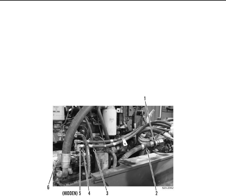
65. Loosen two tube nuts (Figure 37, Item 4) and remove hoses (Figure 37, Item 3) and O-rings (Figure 37, Item 5)
from brake and fan pump (Figure 37, Item 6). Discard O-rings.
66. Remove tiedown strap (Figure 37, Item 1) from hoses (Figure 37, Item 2). Discard tiedown strap.
Figure 37. Brake and Fan Pump.
0177