
TM 5-3805-298-23-2
0177
REMOVAL CONTINUED
NOTE
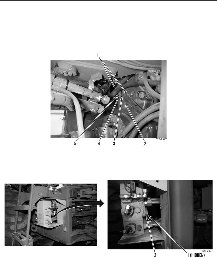
Note location of spacers for installation purposes.
59. Remove two bolts (Figure 31, Item 5), washers (Figure 31, Item 4), P-clamps (Figure 31, Item 1) and spacers
(Figure 31, Item 3) from bracket (Figure 31, Item 2).
Figure 31. Bracket.
0177
60. Remove two O-rings (Figure 32, Item 1) from implement control valve fittings (Figure 32, Item 2). Discard
O-rings.
Figure 32. Implement Control Valve.
0177