
TM 5-3805-298-23-2
0177
INSTALLATION CONTINUED
NOTE
Route wiring harness and cables and install electrical connections as noted during
removal.
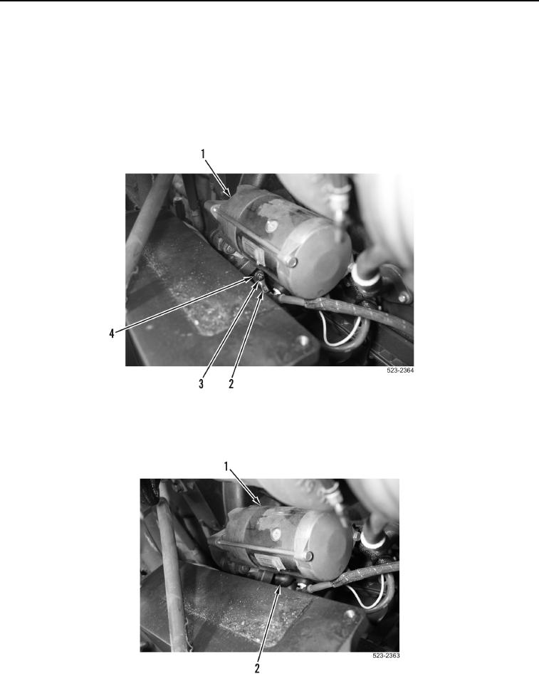
22. Install negative cable (Figure 67, Item 2), washer (Figure 67, Item 4) and bolt (Figure 67, Item 3) on starter
(Figure 67, Item 1).
Figure 67. Starter.
0177
23. Slide boot (Figure 68, Item 2) on starter (Figure 68, Item 1).
Figure 68. Starter.
0177