
TM 5-3805-298-23-2
0177
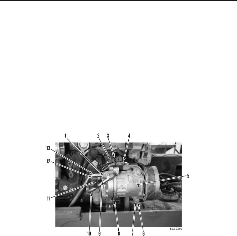
INSTALLATION CONTINUED
27. Install A/C compressor (Figure 71, Item 5), ladder clip (Figure 71, Item 8), four washers (Figure 71, Item 7) and
bolts (Figure 71, Item 6) on machine.
28. Connect engine wiring harness connector (Figure 71, Item 12) to A/C high pressure switch (Figure 71,
Item 11).
CAUTION
Remove all caps from openings and component connections during installation. Failure to
follow this caution may result in damage to equipment.
NOTE
Install hoses and tubes as noted during removal.
29. Install two tubes (Figure 71, Item 10 and 13), clamp (Figure 71, Item 1) and bolt (Figure 71 Item 9) on A/C
compressor (Figure 71, Item 5).
30. Connect A/C compressor clutch connector (Figure 71, Item 4) to engine wiring harness connector (Figure 71,
Item 2).
31. Install new tiedown strap (Figure 71, Item 3) on engine wiring harness connector (Figure 71, Item 2).
Figure 71. A/C Compressor.
0177