
TM 5-3805-298-23-2
0178
ENGINE TRANSFER OF PARTS REMOVAL
000178
CAUTION
Cap all openings along with component connections during removal to protect against
contamination. Failure to follow this caution may result in damage to equipment.
NOTE
Tag and mark all hoses and tubes to aid installation.
Note routing of hoses and tubes for installation.
1. Install engine on stand. See procedure in this work package.
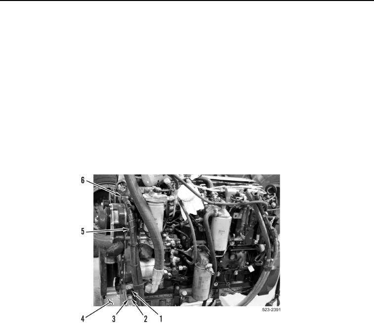
2. Loosen two clamps (Figure 12, Item 6) and remove coolant hoses (Figure 12, Item 5) from engine.
3. Remove bolt (Figure 12, Item 2), washer (Figure 12, Item 3) and bracket(Figure 12, Item 1) from engine mount
bracket (Figure 12, Item 4).
Figure 12. Coolant Hoses.
0178