
TM 5-3805-298-23-2
0178
REMOVE ENGINE FROM STAND CONTINUED
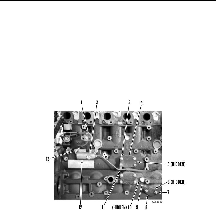
6. Position wastegate solenoid (Figure 46, Item 12) on engine.
7. Install two bolts (Figure 46, Item 13) on wastegate solenoid (Figure 46, Item 12).
CAUTION
Remove all caps from hydraulic openings and component connections during installation.
Failure to follow this caution may result in damage to equipment.
8. Install line (Figure 46, Item 1) and tighten tube nut (Figure 46, Item 2) on wastegate solenoid
(Figure 46, Item 12).
9. Install new O-ring (Figure 46, Item 10) and plug (Figure 46, Item 9) on engine.
10. Install new gasket (Figure 46, Item 6), plate (Figure 46, Item 8) and two bolts (Figure 46, Item 7) on engine.
11. Install two new gaskets (Figure 46, Item 5), plates (Figure 46, Item 4), P-clamp (Figure 46, Item 11) and eight
bolts (Figure 46, Item 3) on engine.
Figure 46. Wastegate Solenoid.
0178