
TM 5-3805-298-23-2
0178
REMOVE ENGINE FROM STAND CONTINUED
NOTE
Refer to removal for position and orientation of spacer.
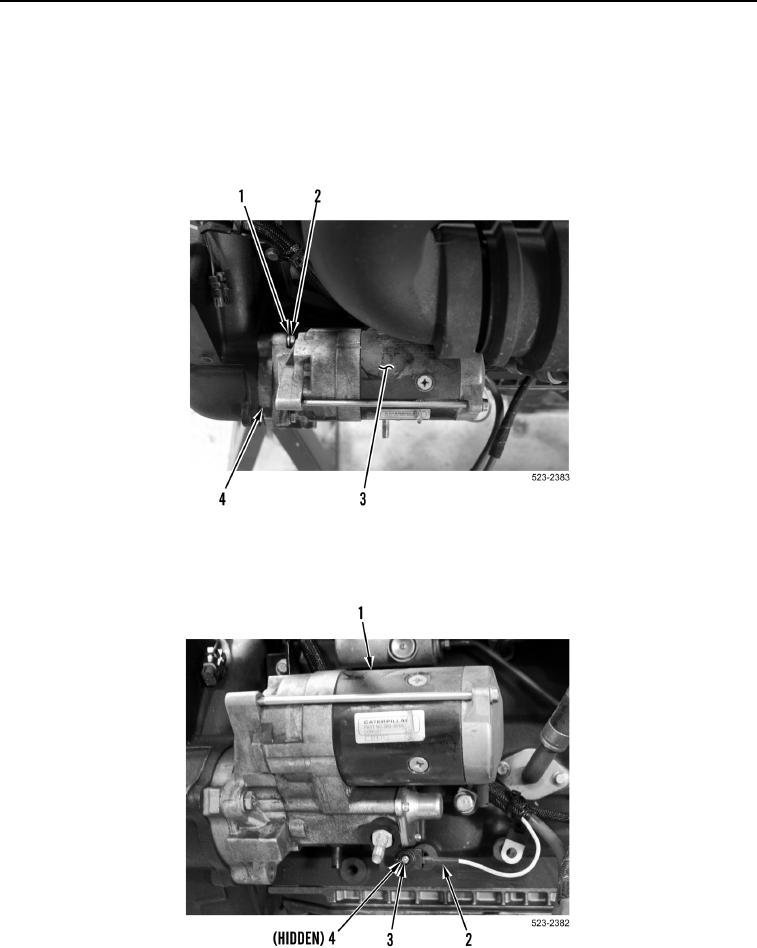
26. Install spacer (Figure 53, Item 4), starter (Figure 53, Item 3), two washers (Figure 53, Item 1) and bolts
(Figure 53, Item 2) on engine.
Figure 53. Starter.
0178
27. Install wire harness connector (Figure 54, Item 2) and screw (Figure 54, Item 3) on starter (Figure 54, Item 1).
Figure 54. Starter.
0178