
TM 5-3805-298-23-2
0178
REMOVE ENGINE FROM STAND CONTINUED
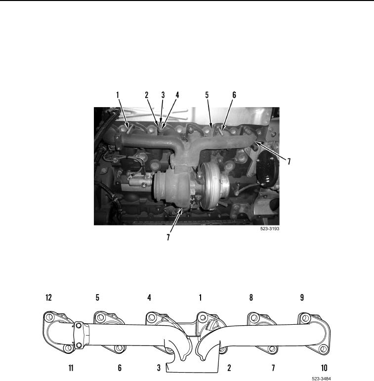
12. Install two guide studs (Figure 47, Item 1 and 6) on engine.
13. Install two new gaskets (Figure 47, Item 5), exhaust manifold and turbocharger assembly (Figure 47, Item 7),
ten spacers (Figure 47, Item 2), washers (Figure 47, Item 3) and bolts (Figure 47, Item 4) on engine.
14. Remove two guide studs (Figure 47, Item 1 and 6) from engine, and install two spacers (Figure 47, Item 1),
washers (Figure 47, Item 5), and bolts (Figure 47, Item 4).
Figure 47. Exhaust Manifold and Turbocharger Assembly.
0178
15. Tighten 12 bolts in sequence shown in Figure 48. Tighten bolts to 32 lb-ft (43 Nm).
Figure 48. Bolt Tightening Sequence.
0178