
TM 5-3805-298-23-2
0192
ENGINE OIL COOLER REMOVAL
000192
NOTE
Cap or plug hoses, tube, and open ports during removal.
Tag and mark hoses and tube to aid installation.
Note hose and tube routing to aid installation.
Care must be taken to ensure that fluids are contained during performance of inspection,
maintenance, testing, adjusting and repair of the product. Be prepared to collect the fluid
with suitable containers before opening any compartment or disassembling any
component containing fluids.
Dispose of all fluids according to local regulations and mandates.
1. Remove engine oil filter base. (See procedure in this work package.)
2. Drain engine coolant (WP 0228).
3. Crankcase breather base removed (WP 0189).
4. Engine ECM and bracket removed (WP 0265).
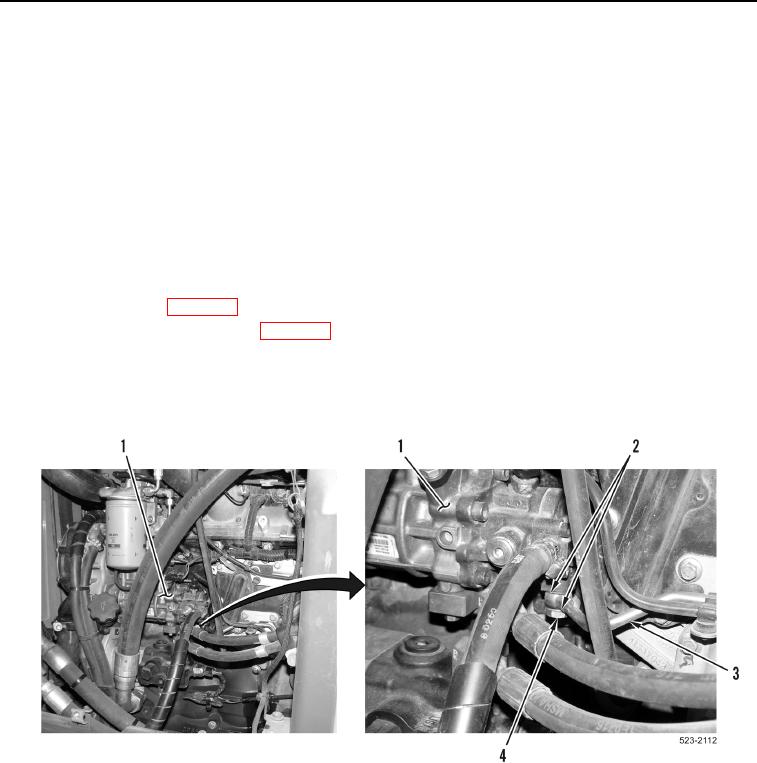
5. Remove fluid passage bolt (Figure 3, Item 4) and two sealing washers (Figure 3, Item 2) from fuel injection
pump (Figure 3, Item 1) and fuel line (Figure 3, Item 3). Discard sealing washers.
Figure 3. Fuel Injection Pump.
0192