
TM 5-3805-298-23-2
0192
ENGINE OIL COOLER REMOVAL CONTINUED
NOTE
Note position and routing of fuel lines.
Note position and quantity of tiedown straps.
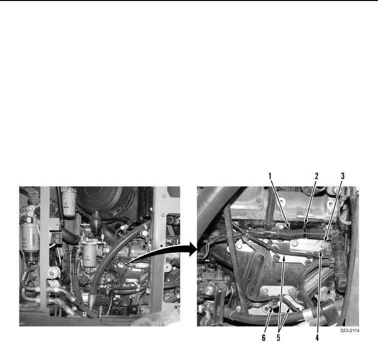
8. Remove two fuel lines (Figure 5, Item 5) from clips (Figure 5, Item 6). Position fuel lines aside.
9. Remove tiedown straps (Figure 5, Item 2) from engine control wiring harness (Figure 5, Item 1). Position
engine control wiring harness aside.
NOTE
Note position and orientation of bolts and brackets to aid installation.
10. Remove six bolts (Figure 5, Item 3) and four brackets (Figure 5, Item 4) from machine.
Figure 5. Engine Control Harness.
0192