
TM 5-3805-298-23-2
0192
ENGINE OIL COOLER INSTALLATION CONTINUED
NOTE
Install bolts and brackets as noted during removal.
Install tiedown straps as noted during removal.
Install fuel lines as noted during removal.
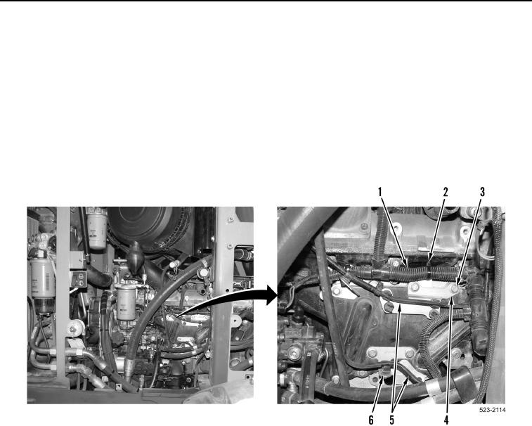
3. Install four brackets (Figure 9, Item 4) and six bolts (Figure 9, Item 3) on machine.
4. Install new tiedown straps (Figure 9, Item 2) on engine control wiring harness (Figure 9, Item 1).
5. Install two fuel lines (Figure 9, Item 5) in clips (Figure 9, Item 6).
Figure 9. Engine Control Harness.
0192