
TM 5-3805-298-23-2
0198
REMOVAL CONTINUED
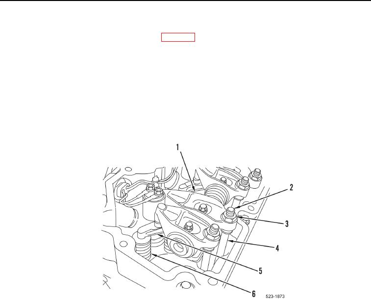
1. Rotate crankshaft until rocker arms (Figure 1, Item 1) for appropriate cylinder are in correct position to adjust
valve lash. Refer to Valve Lash Adjustment in WP 0186.
2. Loosen nuts (Figure 1, Item 3) until cup of pushrods (Figure 1, Item 4) can be withdrawn from ball of adjusters
(Figure 1, Item 2).
CAUTION
Do not interchange location or orientation of used valve links. Make a temporary mark on
valve links to preserve location and orientation. Failure to follow this caution may cause
premature wear.
3. Remove two valve links (Figure 1, Item 5) from four valve springs (Figure 1, Item 6).
Figure 1. Valve Link Replacement.
0198