
TM 5-3805-298-23-2
0224
CLEANING AND INSPECTION
000224
Clean and inspect all parts IAW Mechanical General Maintenance Instructions (WP 0172).
END OF TASK
ETHER VALVE AND BRACKET INSTALLATION
000224
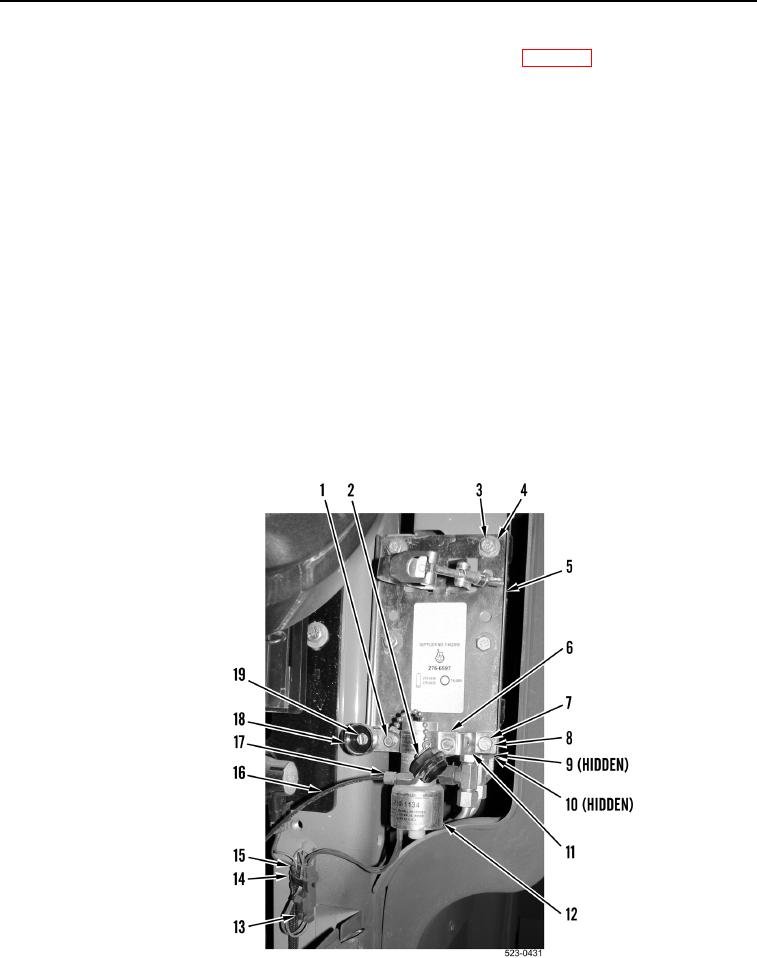
1. Install bracket (Figure 5, Item 5), four washers (Figure 5, Item 4), and bolts (Figure 5, Item 3) on machine.
2. Install bracket (Figure 5, Item 11), two washers (Figure 5, Item 8), bolts (Figure 5, Item 7), new lockwashers
(Figure 5, Item 9), and nuts (Figure 5, Item 10) on machine.
3. Install ether valve (Figure 5, Item 12), bracket (Figure 5, Item 6), cap and tether (Figure 5, Item 2), and two
bolts (Figure 5, Item 1) on machine.
4. Install housing (Figure 5, Item 18) and bolt (Figure 5, Item 19) on bracket (Figure 5, Item 6).
5. Install cap and tether (Figure 5, Item 2) on housing (Figure 5, Item 18).
NOTE
Install electrical connectors and wiring harness as tagged during removal.
6. Connect rear frame harness connector (Figure 5, Item 13) on ether valve connector (Figure 5, Item 15).
7. Install new tiedown strap (Figure 5, Item 14) on ether valve connector (Figure 5, Item 15).
8. Install line (Figure 5, Item 16) and tube nut (Figure 5, Item 17) on ether valve (Figure 5, Item 12).
Figure 5. Valve and Bracket.
0224