
TM 5-3805-298-23-2
0235
REMOVAL CONTINUED
NOTE
Note position tiedown strap to aid installation.
Tag and mark wiring harness connectors and note wiring harness routing to aid
installation.
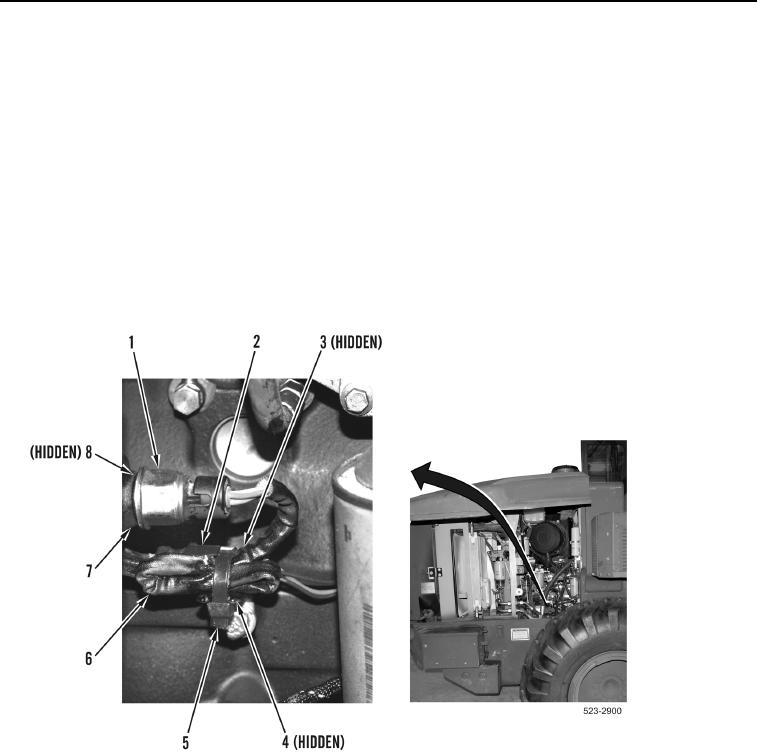
5. Remove tiedown strap (Figure 4, Item 5) from engine wiring harness connector (Figure 4, Item 3), brake
charging oil pressure sensor wiring harness (Figure 4, Item 6), and ladder clip (Figure 4, Item 4). Discard
tiedown strap.
6. Disconnect engine wiring harness connector (Figure 4, Item 3) from brake charging oil pressure sensor
connector (Figure 4, Item 2).
7. Remove brake charging oil pressure sensor (Figure 4, Item 1) and O-ring (Figure 4, Item 8) from hydraulic
cooling fan gear pump (Figure 4, Item 7). Discard O-ring.
Figure 4. Brake Charging Oil Pressure Sensor.
0235