
TM 5-3805-298-23-2
0235
REMOVAL CONTINUED
NOTE
Note orientation of fittings to aid installation.
Tag and mark fittings to aid installation.
Cap or plug open ports and fittings to protect against contamination.
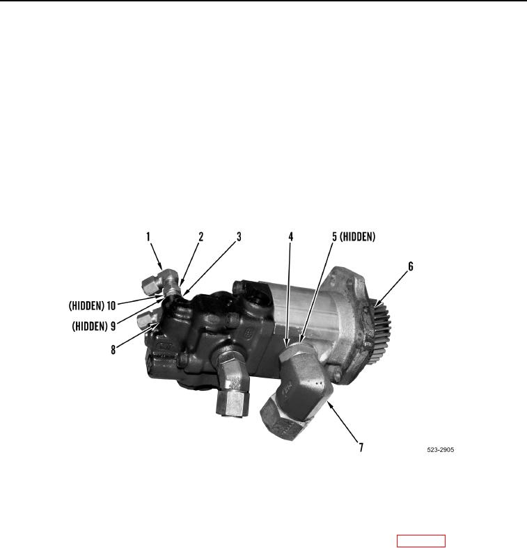
14. Remove gasket (Figure 9, Item 6) from hydraulic cooling fan gear pump (Figure 9, Item 8). Discard gasket.
15. Loosen three jam nuts (Figure 9, Item 4) and remove elbow fittings (Figure 9, Item 7) and three O-rings
(Figure 9, Item 5) from hydraulic cooling fan gear pump (Figure 9, Item 8). Discard O-rings.
16. Loosen tube nut (Figure 9, Item 2) and remove elbow fitting (Figure 9, Item 1) and O-ring (Figure 9, Item 10)
from fitting (Figure 9, Item 3).
17. Remove fitting (Figure 9, Item 3) and O-ring (Figure 9, Item 9) from pump (Figure 9, Item 8).
Figure 9. Hydraulic Cooling Fan Gear Pump Fittings.
0235
END OF TASK
CLEANING AND INSPECTION
000235
Clean and inspect all components IAW Mechanical General Maintenance Instructions (WP 0172).
END OF TASK