
TM 5-3805-298-23-2
0235
REMOVAL CONTINUED
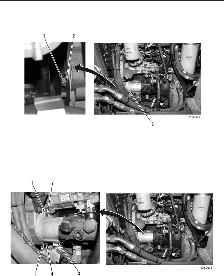
10. Remove bolt (Figure 7, Item 1) and washer (Figure 7, Item 2) from hydraulic cooling fan gear pump
(Figure 7, Item 3).
Figure 7. Hydraulic Cooling Fan Gear Pump Bolt and Washer.
0235
11. Remove bolt (Figure 8, Item 4) and washer (Figure 8, Item 5) from hydraulic cooling fan gear pump
(Figure 8, Item 3).
12. Remove four bolts (Figure 8, Item 2) and washers (Figure 8, Item 1) from hydraulic cooling fan gear pump
(Figure 8, Item 3).
13. Remove hydraulic cooling fan gear pump (Figure 8, Item 3) from machine.
Figure 8. Hydraulic Cooling Fan Gear Pump Bolts and Washers.
0235