
TM 5-3805-298-23-2
0235
INSTALLATION CONTINUED
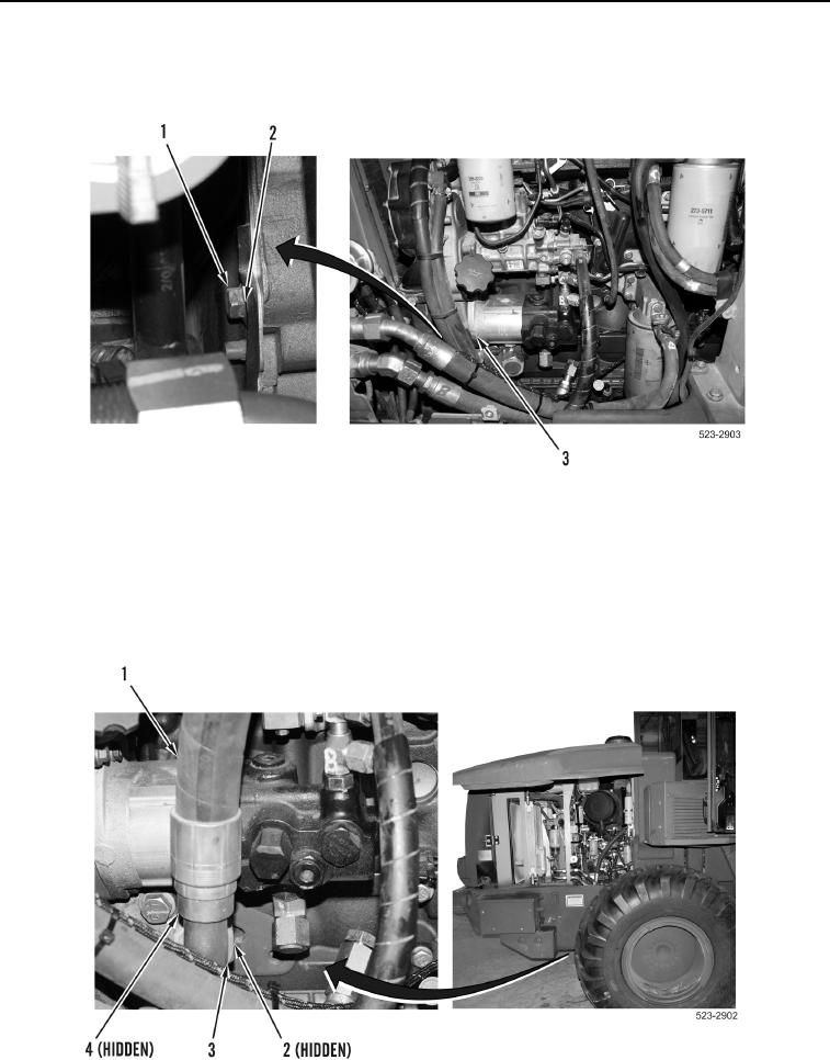
7. Install washer (Figure 11, Item 2) and bolt (Figure 11, Item 1) on hydraulic cooling fan gear pump
(Figure 11, Item 3).
Figure 11. Hydraulic Cooling Fan Gear Pump Bolt and Washer.
0235
NOTE
Remove cap or plug and install hose noted during removal.
8. Install new O-ring (Figure 12, Item 2), hose (Figure 12, Item 1), and tube nut (Figure 12, Item 3) on elbow fitting
(Figure 12, Item 4).
Figure 12. Large Tube Nut, Hose, and O-ring.
0235