
TM 5-3805-298-23-4
0371
INSTALLATION CONTINUED
NOTE
Install hoses as noted during removal.
Remove caps from hoses and fittings prior to installation.
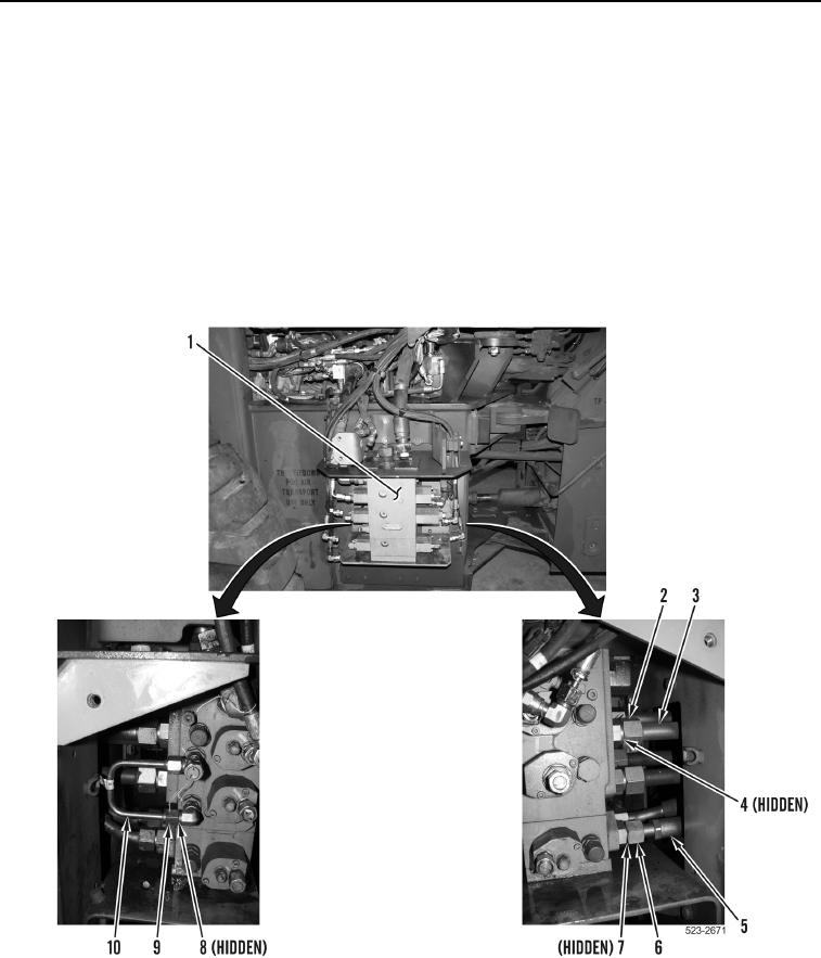
13. Install four new O-rings (Figure 14, Item 4), tubes (Figure 14, Item 3), and tube nuts (Figure 14, Item 2) on
main control valve (Figure 14, Item 1).
14. Install two new O-rings (Figure 14, Item 7), hoses (Figure 14, Item 5), and tube nuts (Figure 14, Item 6) on
main control valve (Figure 14, Item 1).
15. Install two new O-rings (Figure 14, Item 8), tube (Figure 14, Item 10) and two tube nuts (Figure 14, Item 9) on
main control valve (Figure 14, Item 1).
Figure 14. Hoses and Tubes.
0371