
TM 5-3805-298-23-4
0371
REMOVAL CONTINUED
NOTE
Note orientation and position of fittings to aid installation.
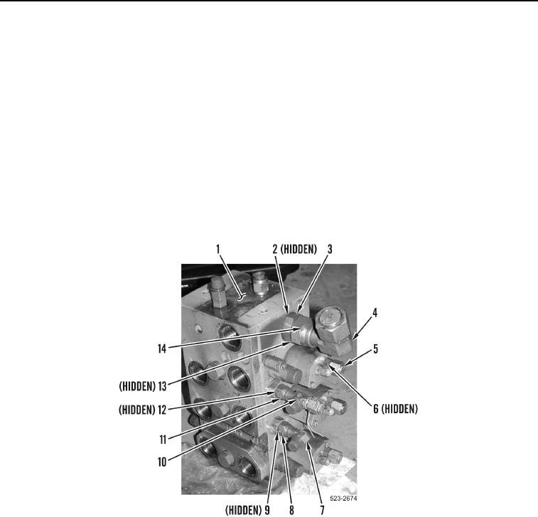
17. Loosen tube nut (Figure 9, Item 14) and remove elbow fitting (Figure 9, Item 4) and O-ring (Figure 9, Item 13)
from main control valve (Figure 9, Item 1). Discard O-ring.
18. Remove fitting (Figure 9, Item 3) and O-ring (Figure 9, Item 2) from main control valve (Figure 9, Item 1).
19. Loosen tube nut (Figure 9, Item 8) and remove elbow fitting (Figure 9, Item 7) and O-ring (Figure 9, Item 9)
from main control valve (Figure 9, Item 1). Discard O-ring.
20. Loosen tube nut (Figure 9, Item 11) and remove T- fitting (Figure 9, Item 10) and O-ring (Figure 9, Item 12)
from main control valve (Figure 9, Item 1). Discard O-ring.
21. Remove three fittings (Figure 9, Item 5) and O-rings (Figure 9, Item 6) from main control valve
(Figure 9, Item 1). Discard O-rings.
Figure 9. Elbow Fittings.
0371