
TM 5-3805-298-23-4
0371
REMOVAL CONTINUED
NOTE
Note orientation and position of fittings to aid installation.
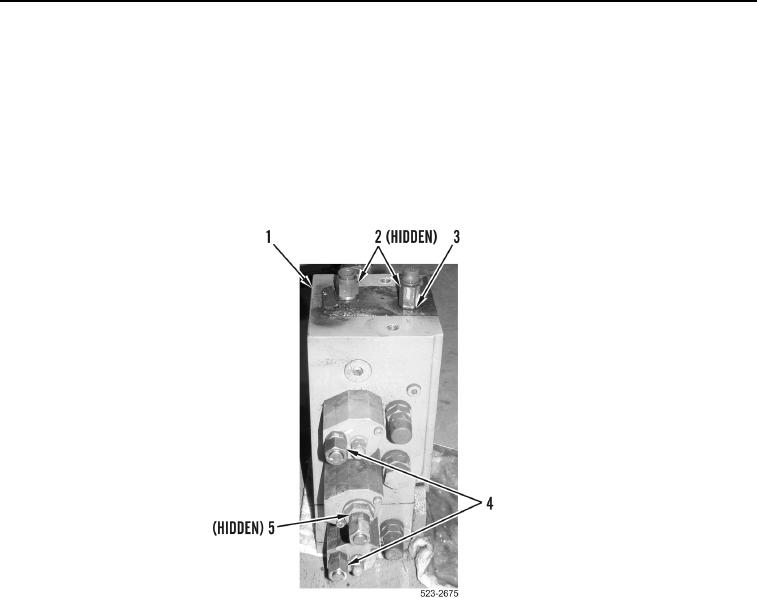
22. Remove three fittings (Figure 10, Item 4) and O-rings (Figure 10, Item 5) from main control valve
(Figure 10, Item 1). Discard O-rings.
23. Remove two fittings (Figure 10, Item 2) and O-rings (Figure 10, Item 3) from main control valve
(Figure 10, Item 1). Discard O-rings.
Figure 10. Top Fittings.
0371
END OF TASK
CLEANING AND INSPECTION
000371
Clean and inspect all parts IAW Mechanical General Maintenance Instructions (WP 0172).
END OF TASK
INSTALLATION
000371
NOTE
Install fitting as noted during removal.
1. Install two new O-rings (Figure 10, Item 3) and fittings (Figure 10, Item 2) on main control valve
(Figure 10, Item 1).
2. Install three new O-rings (Figure 10, Item 5) and fittings (Figure 10, Item 4) on main control valve
(Figure 10, Item 1).