
8
TM 5-3805-298-23-4
FIELD MAINTENANCE
-
COMBINATION TILT RELIEF VALVE REPLACEMENT
0373
Removal, Cleaning and Inspection, Installation
INITIAL SETUP
Materials/Parts - Continued
Tools and Special Tools
0
0
Tool Kit, General Mechanic's
O-ring, 4J-5477 (WP 0432, Item 122) (2)
0
(WP 0431, Item 162)
O-ring, 6V-8397 (WP 0432, Item 140)
0
0
Gloves, Rubber (WP 0431, Item 63)
O-ring, 6V-8398 (WP 0432, Item 141) (4)
0
0
Pan, Drain (WP 0431, Item 89)
0
References
0
Goggles
0
WP 0172
0
Materials/Parts
0
Equipment Conditions
0
Rag, Wiping (WP 0430, Item 27)
0
Machine parked (TM 5-3805-298-10)
Tag, Marker (WP 0430, Item 35)
0
0
Right side lower cab access panels removed
Tiedown Strap, Electrical Components
(WP 0347).
(WP 0430, Item 40)
0
0
Hydraulic tank drained (WP 0368).
O-ring, 3J-1907 (WP 0432, Item 109) (2)
0
0
O-ring, 3J-7354 (WP 0432, Item 111)
Estimated Time to Complete
0
0
O-ring, 3K-0360 (WP 0432, Item 112) (2)
3.0 Hr
0
0
REMOVAL
000373
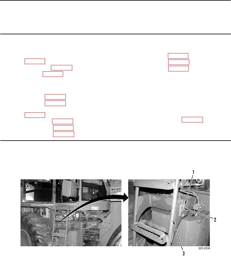
1. Remove four bolts (Figure 1, Item 1) washers (Figure 1, Item 2) and ladder (Figure 1, Item 3) from machine.
Figure 1. Ladder.
0373