
TM 5-3805-298-23-4
0375
REMOVAL CONTINUED
NOTE
Tag and mark hydraulic hoses and note hydraulic hose routing to aid installation.
Tag and mark wiring harness connectors and note wiring harness routing to aid
installation.
Note position and orientation of elbow fittings to aid installation.
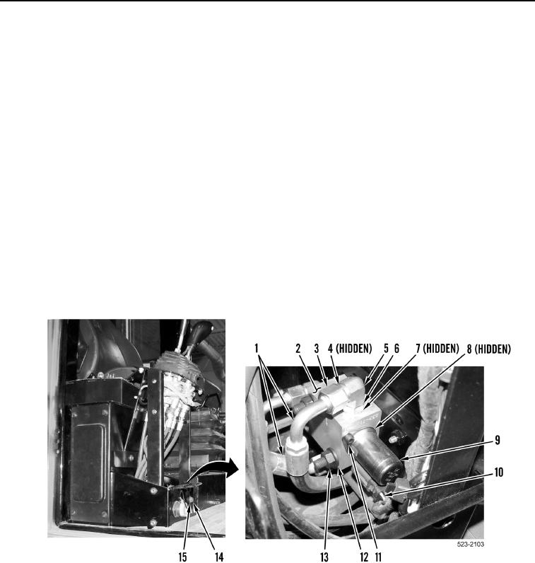
4. Disconnect lower cab wiring harness connector (Figure 3, Item 10) from hydraulic lock-out solenoid (Figure 3,
Item 9).
5. Remove two nuts (Figure 3, Item 13), washers (Figure 3, Item 12), bolts (Figure 3, Item 14), and washers
(Figure 3, Item 15) from hydraulic lock-out valve (Figure 3, Item 2).
6. Loosen three tube nuts (Figure 3, Item 3) and remove three hoses (Figure 3, Item 1) and O-rings (Figure 3,
Item 4) from elbow fittings (Figure 3, Item 5). Discard O-rings.
7. Remove hydraulic lock-out valve (Figure 3, Item 2) from machine.
8. Remove two bolts (Figure 3, Item 11), hydraulic lock-out solenoid (Figure 3, Item 9), and four O-rings
(Figure 3, Item 8) from hydraulic lock-out valve (Figure 3, Item 2).
9. Loosen three jam nuts (Figure 3, Item 6), and remove three elbow fittings (Figure 3, Item 5) and O-rings
(Figure 3, Item 7) from hydraulic lock-out valve (Figure 3, Item 2). Discard O-rings.
Figure 3. Hydraulic Lock-out Valve.
0375
END OF TASK
CLEANING AND INSPECTION
000375
Clean and inspect all parts IAW Mechanical General Maintenance Instructions (WP 0172).
END OF TASK