
TM 5-3805-298-23-4
0386
REMOVAL
000386
WARNING
Lubricating/hydraulic oils can be very slippery. Immediately wipe up any spills. Failure to
follow this warning may result in injury or death to personnel.
CAUTION
Cap all hydraulic openings along with component connections during removal to protect
against contamination. Failure to follow this caution may result in damage to equipment.
NOTE
Tag and mark all hoses to aid installation.
Note routing of hoses for installation.
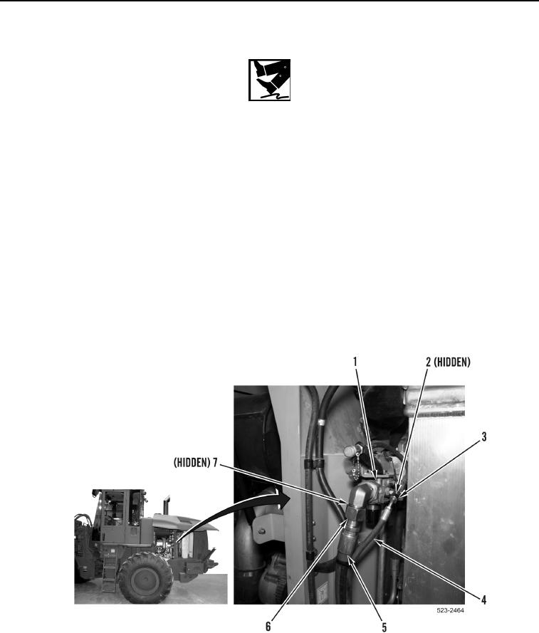
1. Loosen tube nut (Figure 1, Item 6) and remove hose (Figure 1, Item 5) and O-ring (Figure 1, Item 7) from
hydraulic system filter base (Figure 1, Item 1). Discard O-ring.
2. Loosen tube nut (Figure 1, Item 3) and remove hose (Figure 1, Item 4) and O-ring (Figure 1, Item 2) from
hydraulic system filter base (Figure 1, Item 1). Discard O-ring.
Figure 1. Hoses.
0386