TM 5-3805-298-23-4
0386
INSTALLATION
000386
NOTE
Refer to removal for fitting position and orientation.
1. Install new O-ring (Figure 5, Item 15), elbow fitting (Figure 5, Item 5) and tighten jam nut (Figure 5, Item 16) on
hydraulic system filter base (Figure 5, Item 11).
2. Install new O-ring (Figure 5, Item 4) and fitting (Figure 5, Item 3) on elbow fitting (Figure 5, Item 5).
3. Install hose assembly (Figure 5, Item 1) and tighten tube nut (Figure 5, Item 2) on fitting (Figure 5, Item 3).
4. Install new O-ring (Figure 5, Item 10) and hydraulic fluid temperature sensor (Figure 5, Item 9) on hydraulic
system filter base (Figure 5, Item 11).
5. Install new O-ring (Figure 5, Item 8), elbow fitting (Figure 5, Item 6) and tighten jam nut (Figure 5, Item 7) on
hydraulic system filter base (Figure 5, Item 11).
6. Install two new O-rings (Figure 5, Item 12), elbow fittings (Figure 5, Item 14) and tighten jam nuts (Figure 5,
Item 13) on hydraulic system filter base (Figure 5, Item 11).
NOTE
Bracket removal is only necessary if damaged.
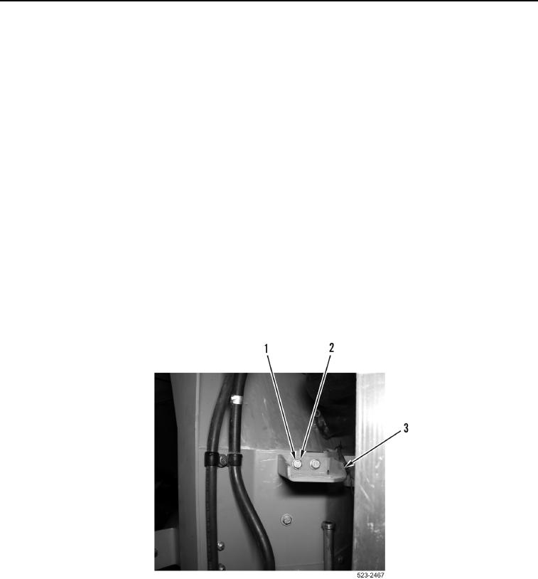
7. Install hydraulic system filter base bracket (Figure 6, Item 3), two washers (Figure 6, Item 2) and bolts
(Figure 6, Item 1) on machine.
Figure 6. Hydraulic System Filter Base Bracket.
0386

