
TM 5-3805-298-23-4
0386
REMOVAL CONTINUED
NOTE
Note position and orientation of fittings for installation purposes.
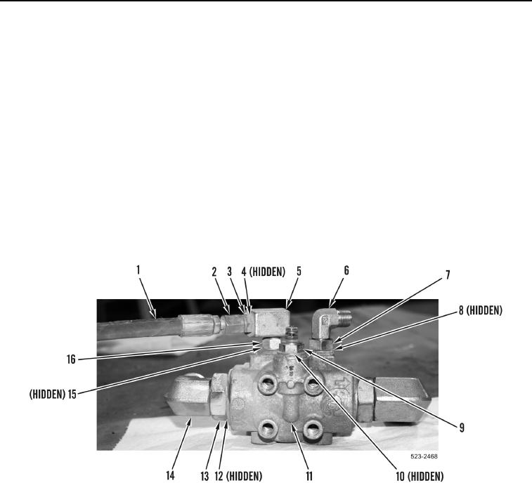
7. Loosen two jam nuts (Figure 5, Item 13) and remove elbow fittings (Figure 5, Item 14) and O-rings (Figure 5,
Item 12) from hydraulic system filter base (Figure 5, Item 11). Discard O-rings.
8. Loosen jam nut (Figure 5, Item 7) and remove elbow fitting (Figure 5, Item 6) and O-ring (Figure 5, Item 8) from
hydraulic system filter base (Figure 5, Item 11). Discard O-ring.
9. Remove hydraulic fluid temperature sensor (Figure 5, Item 9) and O-ring (Figure 5, Item 10) from hydraulic
system filter base (Figure 5, Item 11). Discard O-ring.
10. Loosen tube nut (Figure 5, Item 2) and remove hose assembly (Figure 5, Item 1) from fitting (Figure 5, Item 3).
11. Remove fitting (Figure 5, Item 3) and O-ring (Figure 5, Item 4) from elbow (Figure 5, Item 5). Discard O-ring.
12. Loosen jam nut (Figure 5, Item 16) and remove elbow fitting (Figure 5, Item 5) and O-ring (Figure 5, Item 15)
from hydraulic system filter base (Figure 5, Item 11). Discard O-ring.
Figure 5. Hydraulic System Filter Base Fittings.
0386
END OF TASK
CLEANING AND INSPECTION
000386
Clean and inspect all parts IAW Mechanical General Maintenance Instructions (WP 0172).
END OF TASK