
TM 5-3805-298-23-4
0386
INSTALLATION CONTINUED
CAUTION
Remove all caps from hydraulic openings and component connections during installation.
Failure to follow this caution may result in damage to equipment.
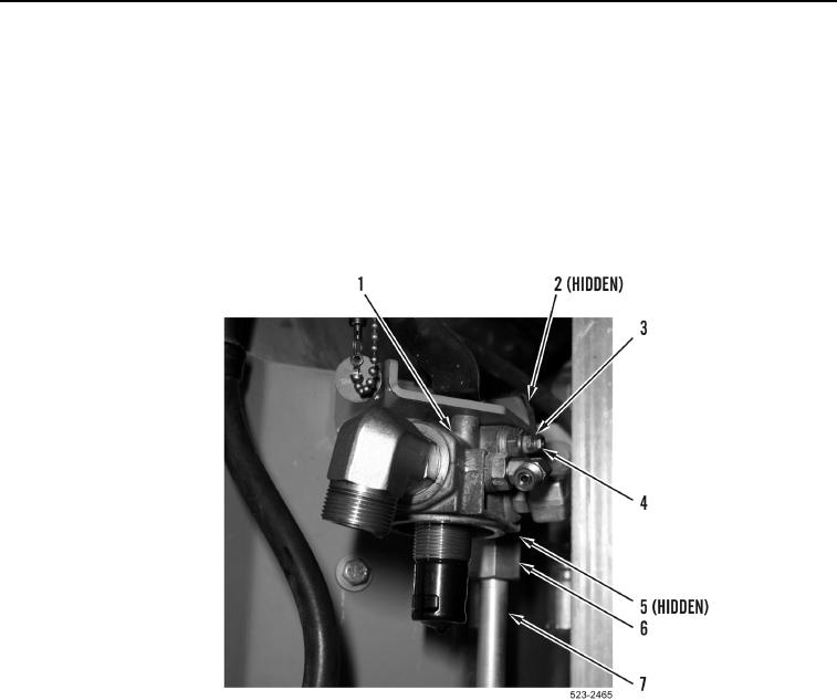
9. Install new O-ring (Figure 8, Item 5), tube (Figure 8, Item 7) and tighten tube nut (Figure 8, Item 6) on hydraulic
system filter base (Figure 8, Item 1).
10. Install rear frame wiring harness terminal (Figure 8, Item 2), washer (Figure 8, Item 3) and nut (Figure 8,
Item 4) on hydraulic system filter base (Figure 8, Item 1).
Figure 8. Tube.
0386